
You’ve heard the pitch: HVDC is the future, the magic bullet for long-distance transmission, the green enabler. Marketing departments love to wax poetic about its efficiency and transformative power. But for those of us who actually have to design, build, and maintain these systems, the reality is far more nuanced. HVDC isn’t just a bigger wire; it’s a fundamentally different beast with its own unique set of headaches, hidden costs, and spectacular failure modes that the brochures conveniently omit.
Long-distance power transmission isn’t simply about pushing more current through a bigger cable. The fundamental physics of AC power transmission introduce limitations that become economically crippling over significant distances. We’re talking about capacitive charging current, inductive voltage drop, and skin effect – phenomena that force us to build complex, reactive power compensation schemes into our AC lines, or worse, accept massive energy losses. This is where the HVDC narrative begins: by eliminating these AC-specific problems, HVDC promises a leaner, more efficient pathway for bulk power. But as always, the devil is in the converter station.
The Problem Nobody Talks About
The dirty secret of AC transmission over long distances or through cables is reactive power flow. For overhead lines exceeding roughly 500-800 km, or submarine cables over 50-80 km, the line’s own capacitance starts to draw significant charging current. This current, while not delivering active power, still flows through the conductors, consuming valuable thermal capacity and causing voltage drops. It’s like paying for a massive vehicle that only carries its own weight. Compensating for this requires shunt reactors, series capacitors, and SVCs – all expensive, bulky, and prone to their own failures.
HVDC sidesteps this entirely. With direct current, there’s no inherent reactive power flow to manage along the line itself. The power factor is always unity on the DC side. This means that for the same conductor cross-section and insulation level, an HVDC line can transmit significantly more active power than its AC counterpart, with lower losses. Sounds great, right? Until you look at the price tag and complexity of the converter stations required at each end. These aren’t just glorified transformers; they are highly sophisticated, fast-acting power electronics systems that are the real brains (and potential Achilles’ heel) of any HVDC scheme.
Technical Deep-Dive
At its core, HVDC involves two converter stations that transform AC power to DC for transmission, and then back to AC at the receiving end. The choice of converter technology dictates much of the system’s behavior, cost, and operational flexibility. We primarily deal with two types: Line Commutated Converters (LCC) and Voltage Source Converters (VSC).
Line Commutated Converters (LCC)
LCC HVDC, also known as Classic HVDC, relies on thyristors (Silicon Controlled Rectifiers, SCRs) arranged in a 6-pulse or 12-pulse bridge configuration. These are robust, high-power semiconductor devices.
- Commutation: LCCs are “line commutated,” meaning they rely on the AC voltage of the connected grid to turn off the thyristors. This makes them inherently dependent on a strong AC grid at the point of connection. If the AC voltage dips or distorts significantly, a commutation failure can occur, leading to a temporary short circuit and system disturbance.
- Reactive Power: LCCs inherently consume reactive power, especially at lower power transfer levels, due to the phase delay required for commutation. This necessitates large shunt capacitor banks and harmonic filters on the AC side to supply reactive power and mitigate the significant harmonics generated by the switching action of the thyristors.
- Cost & Application: LCC systems are generally cheaper for high-power, long-distance, point-to-point transmission where the connected AC grids are strong and stable. They are the workhorses of many bulk power transfer projects globally.
 Image Credit: animalia-life.club
Voltage Source Converters (VSC)
VSC HVDC utilizes Insulated Gate Bipolar Transistors (IGBTs) or Integrated Gate Commutated Thyristors (IGCTs). These are self-commutating devices, meaning they can be turned on and off independently of the AC system voltage.
- Commutation: VSCs actively control the switching of their semiconductors, allowing them to synthesize an AC voltage waveform. This makes them capable of feeding into weak AC grids or even passive loads, and providing black start capability to a de-energized AC network.
- Reactive Power: Unlike LCCs, VSCs can independently control both active and reactive power flow. They can either absorb or inject reactive power into the AC grid, acting like a STATCOM. This reduces the need for external reactive power compensation, resulting in smaller footprints for converter stations.
- Harmonics: VSCs, especially those employing Modular Multilevel Converter (MMC) topologies, produce significantly lower harmonics compared to LCCs, reducing the size and complexity of harmonic filters.
- Cost & Application: VSCs are more expensive than LCCs but offer superior flexibility. They are preferred for offshore wind farm connections, urban in-feeds (where space is at a premium), multi-terminal HVDC grids, and connections to weak or isolated AC systems.
 Image Credit: electrical4u.com
Understanding the complexities of converter control is paramount, especially when considering how these systems react to grid disturbances. For instance, their ability to maintain stability during faults is a critical design consideration, tying into concepts like fault-ride-through.
Key Differences: LCC vs. VSC
The choice between LCC and VSC is not trivial; it’s a fundamental architectural decision with long-term implications for grid stability, operational flexibility, and cost. Here’s a quick rundown of the critical differentiating factors:
| Feature | Line Commutated Converters (LCC) | Voltage Source Converters (VSC) |
|---|---|---|
| Converter Technology | Thyristor (SCR) | IGBT / IGCT (often MMC topology) |
| Commutation | Natural (AC voltage dependent) | Forced (Self-commutated) |
| Reactive Power Control | Coupled with active power, requires compensation | Independent, fast, can be grid-forming |
| AC System Strength Req. | Strong AC source required | Can feed weak/passive AC grids, black start capable |
| Multi-terminal Operation | Complex, often point-to-point | Easier, meshed DC grid potential |
| Black Start Capability | No | Yes |
| Harmonic Content | Higher, requires large filters | Lower, smaller filters (especially MMC) |
| Footprint | Larger (due to filters, reactive compensation) | Smaller |
| Cost (Converter) | Lower | Higher |
| Typical Application | Long-distance, bulk power, stable grids | Offshore wind, urban in-feeds, weak grids, DC grids |
| Losses (Converter) | Slightly lower at rated power | Slightly higher, but wider operating range and flexibility |
| DC Voltage Reversal | Achieved by AC voltage polarity reversal | Achieved by DC current direction reversal |
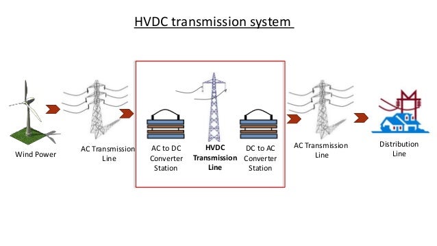 Image Credit: slideshare.net
Implementation Guide
Implementing an HVDC system is a monumental undertaking, far beyond stringing wires. It involves meticulous planning, complex controls, and specialized equipment.
Design Considerations
- Voltage Levels: Modern HVDC systems operate at incredibly high voltages, typically ranging from ±320 kV for VSC up to ±1100 kV for ultra-high voltage LCC lines. The choice depends on power transfer capacity, distance, and insulation requirements. Higher voltages reduce current, thus reducing I²R losses, but increase insulation costs and corona losses.
- Converter Station Siting: These facilities are massive, requiring significant land area. Factors include proximity to existing AC grids, environmental impact, access for heavy transport, and cooling water availability. The filters and reactive power compensation for LCC stations can be particularly space-intensive.
- Ground Electrodes: For monopolar operation (one conductor, ground return) or emergency return in bipolar systems, dedicated ground electrodes are essential. These are typically located several kilometers away from the converter station to minimize interference with existing infrastructure. Careful geological surveys are needed to ensure low soil resistivity and minimize corrosion of pipelines or railway tracks due to telluric currents.
- Control Hierarchy: HVDC systems employ a sophisticated, multi-layered control architecture:
- Master Power Controller: Sets overall power transfer targets, manages power flow between AC grids.
- Pole Controllers: Regulate the DC voltage and current for each pole (positive and negative).
- Valve Group Controllers: Generate the precise firing pulses for individual thyristors or IGBTs based on commands from the pole controller. This hierarchy ensures coordinated operation and rapid response to grid disturbances.
HVDC Converter Station Startup Sequence
The startup sequence of an HVDC converter station is a complex, multi-step process that requires precise synchronization and control. It’s not just flipping a switch.
graph TD
    A["Pre-Energization Checks"] -->|"All OK?"| B["Auxiliary Power On"]
    B --> C["Cooling System Active"]
    C --> D["Converter Valves Ready"]
    D --> E["Control System Initialization"]
    E -->|"Parameters Loaded"| F["AC Breaker Close (AC Side)"]
    F --> G["DC Link Pre-Charging"]
    G -->|"DC Link Voltage OK"| H["Converter Firing Enabled"]
    H --> I["Ramp Up Power Order"]
    I --> J["Synchronized & Operating"]
    J --> K["Monitor & Adjust"]
Failure Modes and How to Avoid Them
This is where the rubber meets the road, or more accurately, where the silicon meets the fault current. HVDC systems, for all their benefits, introduce unique and often brutal failure modes.
The Weak Grid PLL Debacle
I recall a particularly nasty commissioning experience with a new VSC-HVDC link connecting a substantial offshore wind farm to a relatively weak onshore AC grid. The system was designed to provide significant ancillary services, including voltage and frequency support. During initial testing, specifically under a combination of a sudden load rejection on the onshore AC grid and a concurrent, momentary single-phase-to-ground fault on an adjacent distribution feeder, the VSC link experienced a complete and violent collapse of its DC link voltage, tripping both converter stations.
The simulations, of course, showed this scenario was “stable.” The reality was far uglier. The root cause lay in the Phase-Locked Loop (PLL) of the VSC. The PLL, responsible for accurately tracking the grid’s voltage angle and frequency, is the VSC’s eyes and ears. Tuned for nominal, relatively stable grid conditions, it struggled to keep up with the rapidly decaying and heavily distorted AC voltage during the combined fault and load rejection event. The fault induced significant voltage sag and a rapid phase jump. The PLL, operating with a bandwidth deemed “optimal” for steady-state performance, momentarily lost lock.
When the PLL loses lock, the vector control algorithm inside the VSC receives incorrect grid angle information. This leads to mis-firing of the IGBTs, resulting in uncontrolled, high-magnitude current injections that further depress the AC voltage. It’s a positive feedback loop into instability. The VSC’s internal protection, sensing extreme DC overcurrent and undervoltage, then initiated an emergency shutdown to protect the semiconductors.
The solution wasn’t simple. It involved:
- Re-tuning the PLL parameters: Reducing its bandwidth and increasing damping to make it more robust against rapid voltage and phase fluctuations, even if it meant a slightly slower response under ideal conditions.
- Implementing advanced grid synchronization techniques: Exploring more sophisticated PLL structures, such as adaptive filtering or integrating virtual impedance control to improve stability when connected to weak grids.
- Extensive Power Hardware-in-the-Loop (PHIL) testing: This was the crucial step. We had to replicate the dynamic interactions in a controlled environment, connecting the actual VSC control system to a real-time simulator modeling the weak grid and fault conditions. This revealed sensitivities and resonance points that traditional offline simulations had missed.
- Refining fault-ride-through (FRT) logic: Ensuring the converter could actively support the grid during faults, rather than just tripping, by injecting reactive current and maintaining stability.
This incident highlighted that “optimal” control parameters for one operating condition can be catastrophic for another, especially when dealing with the complex, non-linear interactions between power electronics and weak AC grids. It’s a constant battle between speed and stability.
Other Common Failure Modes:
- Commutation Failures (LCC): As mentioned, AC voltage dips, phase unbalance, or high levels of harmonics on the AC side can prevent thyristors from turning off, leading to short circuits within the converter bridge.
- Insulation Degradation: DC voltage stress differs fundamentally from AC. Space charge accumulation within solid dielectrics under DC can lead to localized field enhancements and premature breakdown, especially in cables and bushings.
- Converter Valve Failures: Individual thyristors or IGBTs can fail due to overvoltage, overcurrent, or thermal cycling stress. A single valve failure might not trip the entire pole, but cumulative failures degrade reliability and require planned outages for replacement.
- Control System Malfunctions: Software bugs, communication failures, or incorrect parameter settings can lead to oscillations, power swings, or complete trips. These are often the hardest to diagnose, requiring deep dives into sequence of events recorders and waveform captures.
- DC Line Faults: A DC line fault (e.g., flashover due to lightning or contamination) is incredibly challenging. Unlike AC faults, there’s no natural current zero crossing to interrupt the fault. Clearing DC faults requires either tripping the AC breakers at both ends of the line (depowering the entire link) or using specialized, fast-acting DC circuit breakers, which are still an evolving and expensive technology, particularly for multi-terminal VSC systems.
When NOT to Use This Approach
HVDC is not a panacea. There are definite scenarios where its complexity and cost outweigh its benefits.
- Short Transmission Distances: For overhead lines under ~500 km or submarine cables under ~50 km, the high cost of the converter stations typically makes HVDC uneconomical. The savings in line losses and reactive compensation simply don’t justify the capital expenditure and operational complexity.
- Small Power Transfers: HVDC systems have significant fixed costs associated with the converter stations. For power transfers below a certain threshold (e.g., 100-200 MW, depending on voltage and specific technology), an equivalent AC solution will almost always be cheaper and simpler.
- Highly Meshed AC Networks (Sometimes): While VSC-HVDC offers the potential for multi-terminal and even meshed DC grids, integrating new HVDC links into existing, highly meshed AC networks can introduce new challenges in terms of stability, protection coordination, and dynamic interactions. The benefits of HVDC for incremental capacity additions in an already robust AC network might not always outweigh the added complexity and potential for unforeseen stability issues.
- When Simplicity and Low Maintenance are Paramount: AC systems, despite their own complexities, are generally more mature, understood by a broader range of field personnel, and have a more established supply chain for spares and expertise. HVDC systems, especially VSC, require highly specialized engineering knowledge and maintenance crews. If your operational budget and staff expertise are limited, AC might be the more pragmatic choice.
- Where AC Fault Current Contribution is Crucial: LCC HVDC does not contribute to AC fault current, which can be an advantage for limiting fault levels. However, if the receiving AC grid relies on fault current from connected generation to operate its protective relays effectively, an LCC link might necessitate additional fault current limiting or generation. VSC can contribute fault current, but its characteristics are different from synchronous generators and require careful modeling.
Conclusion
HVDC is a formidable tool for solving specific, high-value transmission problems: long distances, submarine crossings, asynchronous interconnections, and integration of large-scale renewables into weak grids. It offers undeniable efficiency and control advantages over traditional AC for these applications.
However, it is not a magic wand. The cost and complexity of the converter stations, the intricate control systems, and the unique failure modes demand a level of engineering rigor that far exceeds what’s often required for AC infrastructure. Don’t just buy into the “cutting-edge synergies” and “game-changing disruptors” spouted by marketing. Understand the physics, the control theory, and the very real potential for things to go sideways when power electronics interact with a dynamic grid.
For the cynical engineers at GridHacker, the takeaway is clear: HVDC is powerful, but it’s not simple. It requires meticulous design, robust control, and a deep understanding of its limitations and failure mechanisms. Skimp on any of these, and you’ll find yourself debugging oscillations and explaining catastrophic trips to management, wishing you’d just run another AC line.
Hero image: Green grass field under cloudy sky during daytime.. Generated via GridHacker Engine.


